I have been using Satechi 72W car charger in my solar home project to power my laptop for about 3 months. I have noticed that at high load it gets too hot, and I suspected that there might be a bad connection in the car lighter socket, which would contribute to the heat generation. I have decided to take the charger apart, and solder wires directly to the PCB, to eliminate risk for a bad connection.
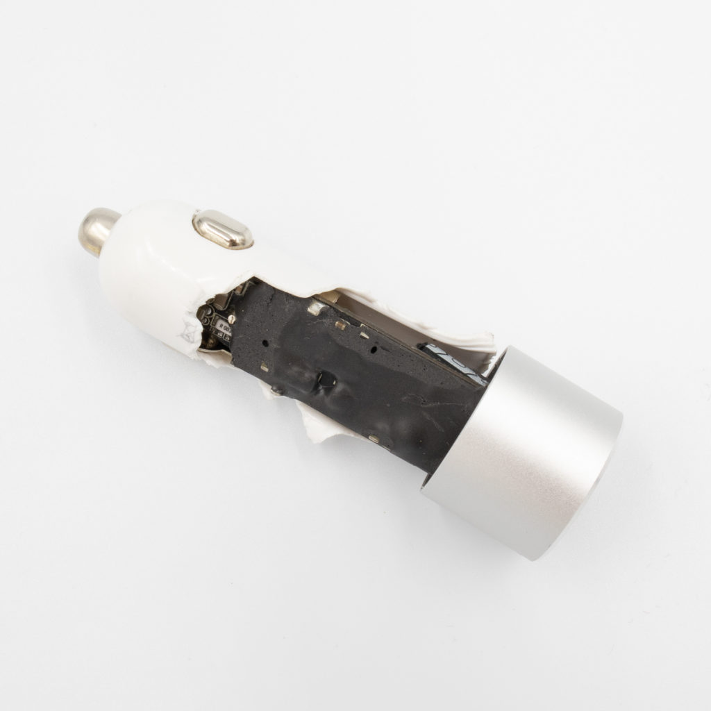
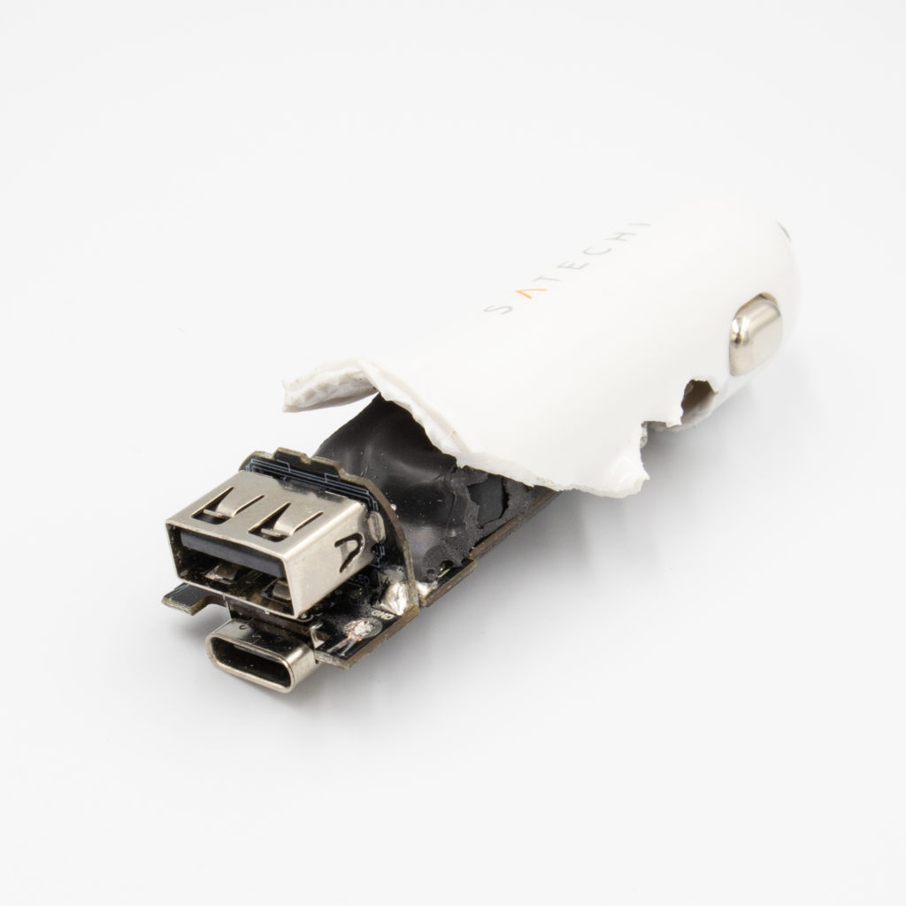
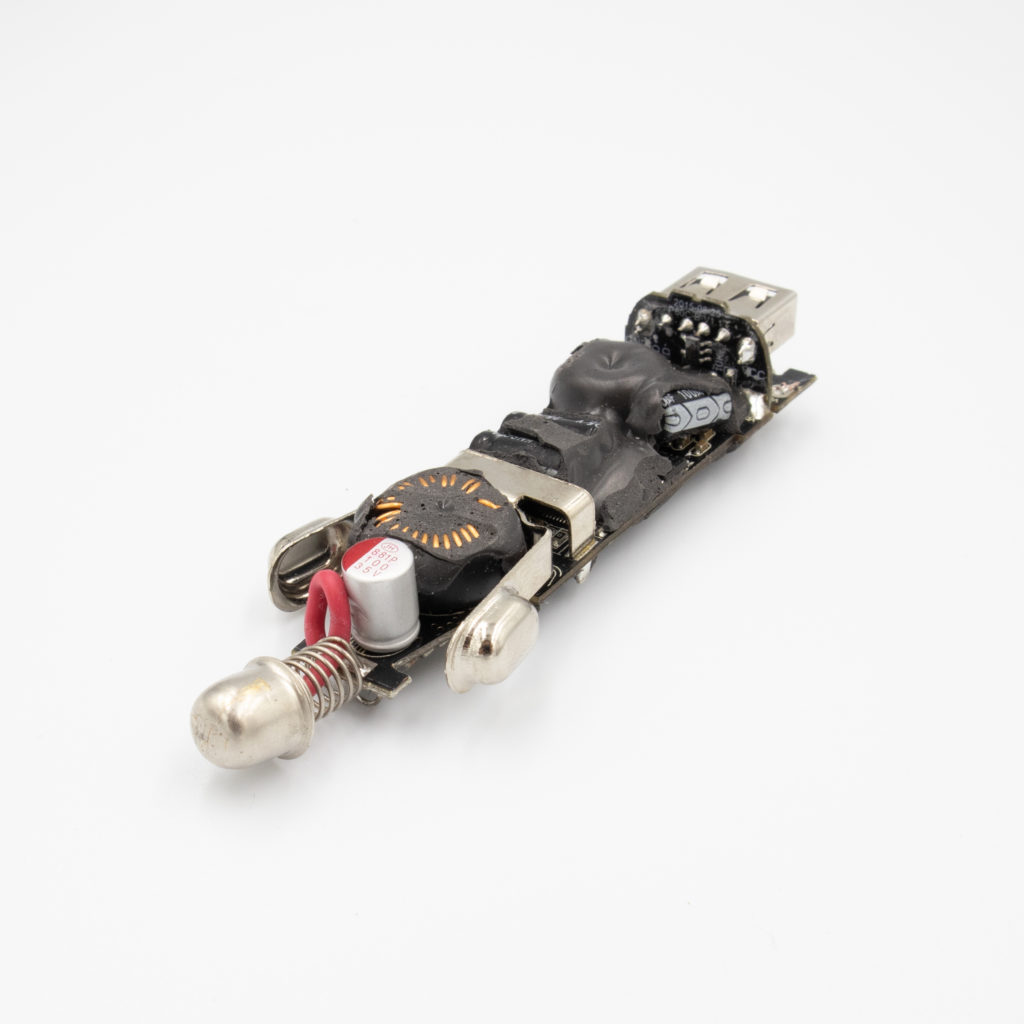
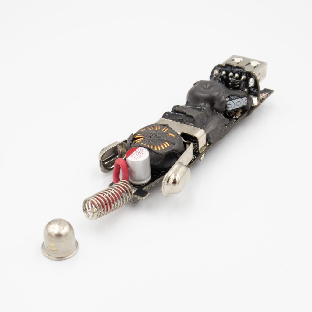
Doing a tear down was not as effortless as expected. It was relatively easy to remove the aluminum cap, but I was struggling with removing the PCB. I had to remove the plastic piece by piece only to find out that I could easily remove the PCB by pressing the ground contacts, so that they go inside of the case. The PCB then just slides out.
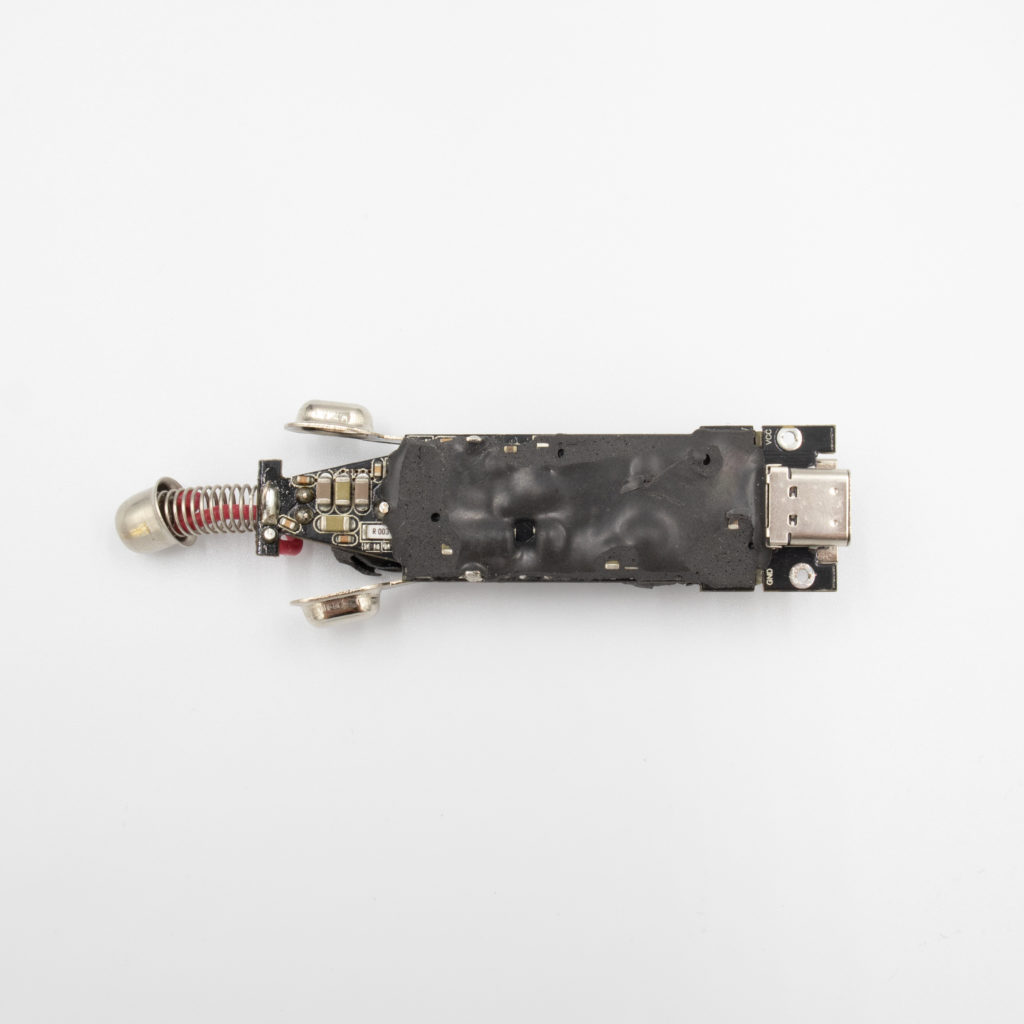
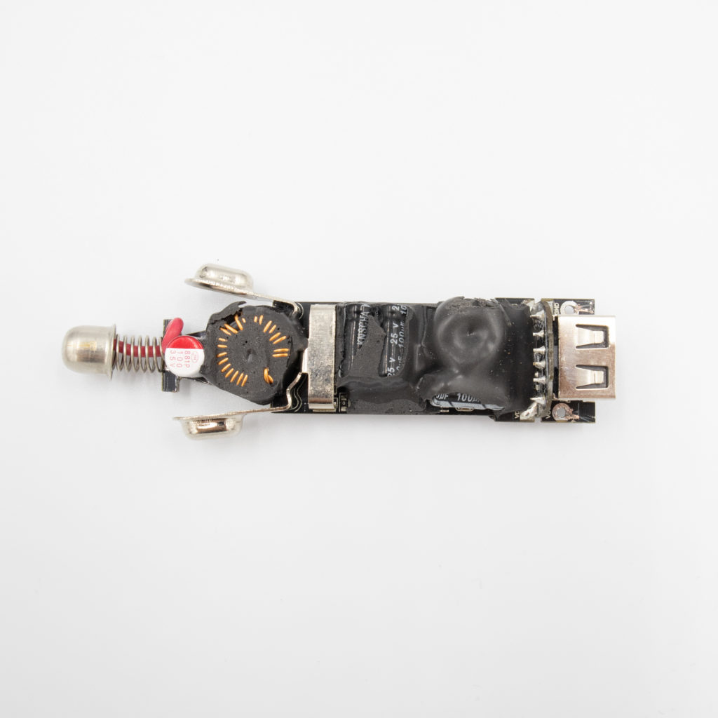
I was a bit surprised to find that the whole board was coated in a soft and thick material. It was easy to remove, and it didn’t seem it would provide any protection against moisture or condensation. The material did feel cold to touch, so it is probably used for improved thermal dissipation.
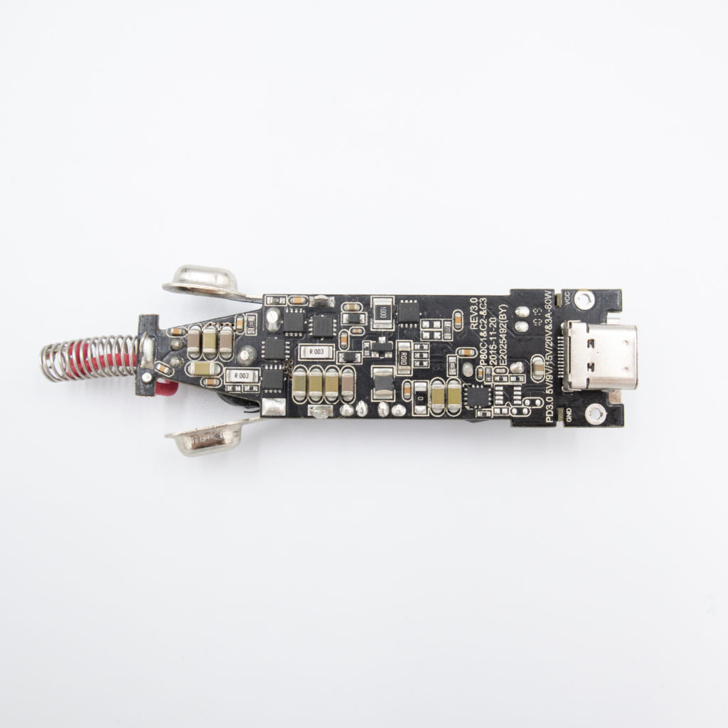
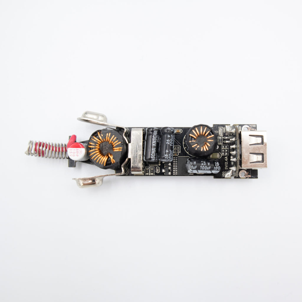
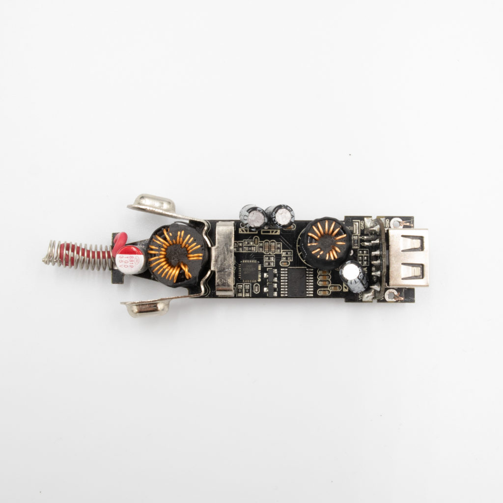
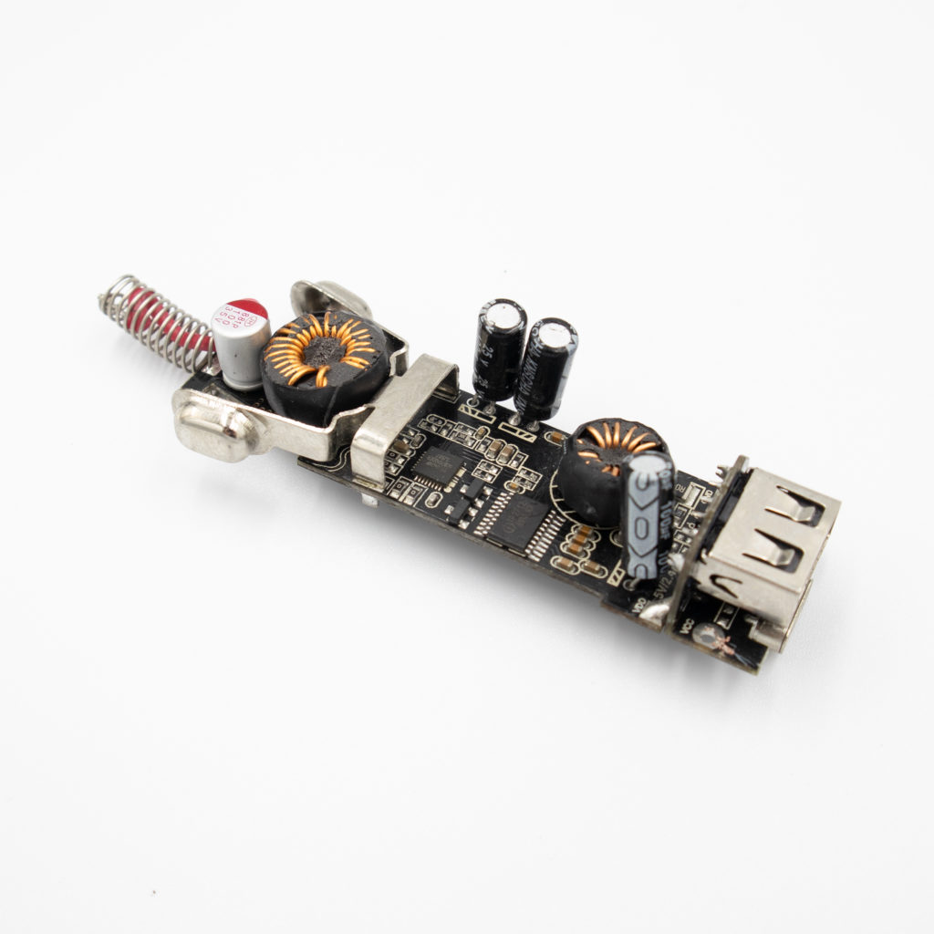
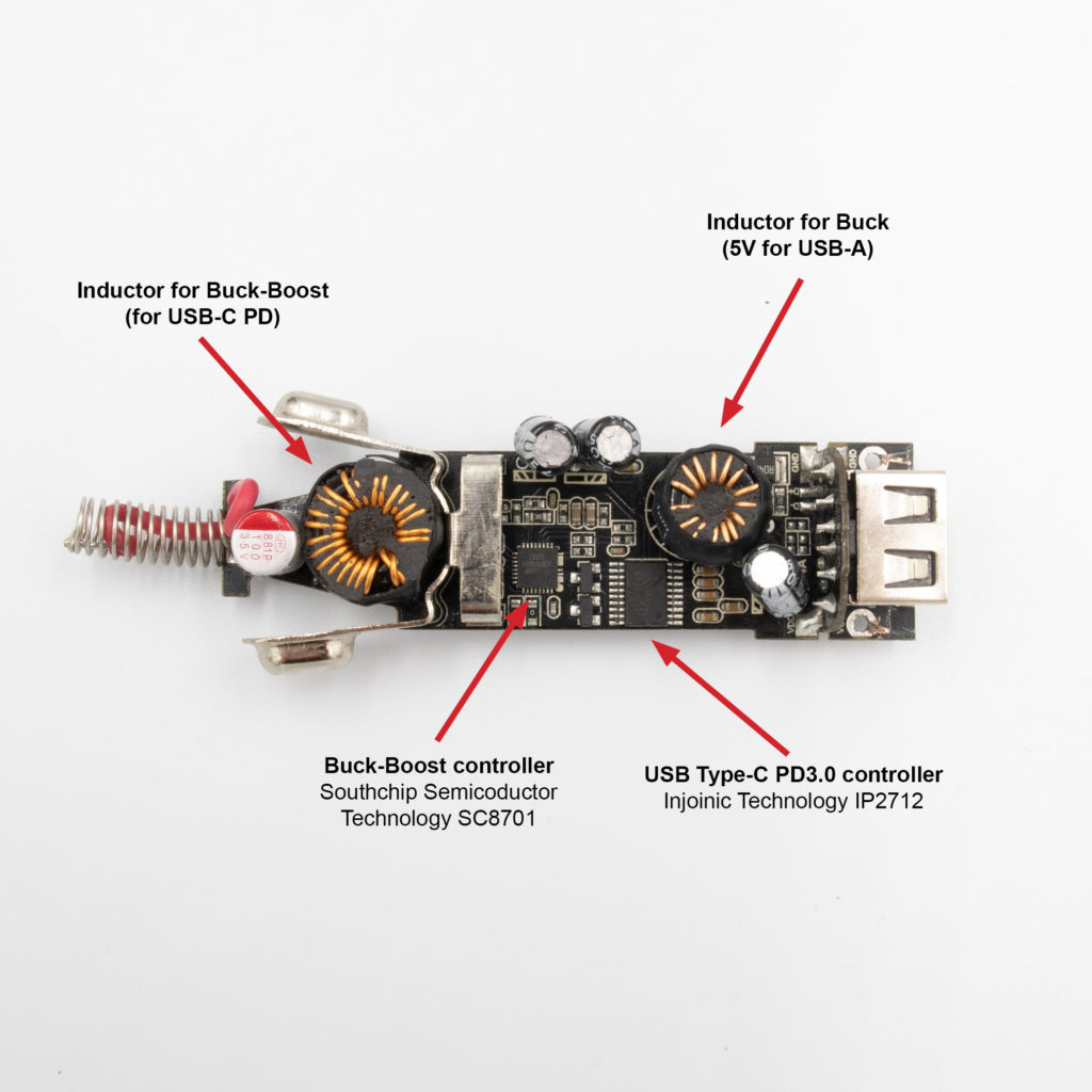
I could identify the key components:
- USB Type-C PD3.0 controller, Injoinic Technology IP2712
- Buck-Boost controller, Southchip Semicoductor Technology SC8701
- N-Channel MOSFET 43A 16mOhm, Techcode TDM3482
There are two inductors, one is used for the buck-boost converter, and another one supposedly for the buck converter (5V for USB-A connector), which I couldn’t identify (marked as AVZ J16 655).
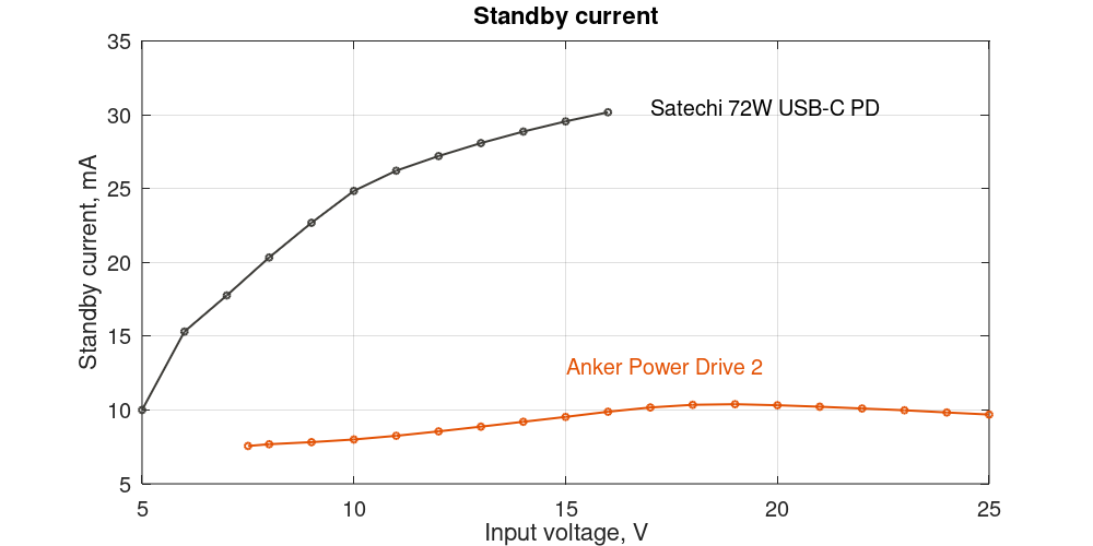
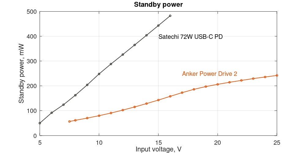
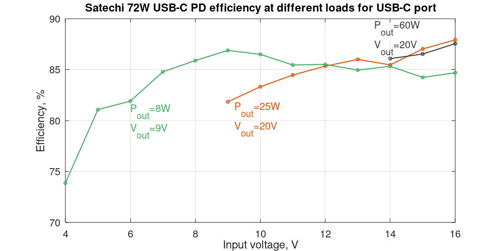
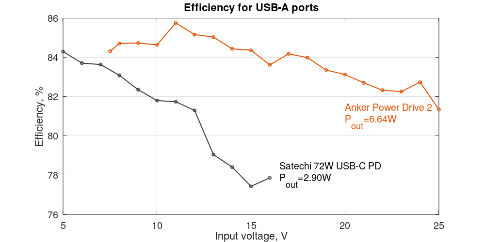
Efficiency and standby power
In one of my previous posts I have also measured the efficiency and standby power.



I’ve been using <a href=”https://dolbear.tech/product-category/headphones/”>Anker car chargers.</a> for years now, and they never disappoint. The price in Bangladesh is quite competitive, considering the durability and fast-charging capabilities these chargers offer. Definitely worth every penny.
Thanks for sharing this teardown and insight! It’s always valuable to see real-world use cases and thermal challenges explored in depth. Direct-soldering to the PCB sounds like a smart move to reduce resistance and heat issues—curious to see how it performs long-term in your solar setup.