Real time data

About one year ago I got an idea of designing solar power manager device. The device would contain an MPPT battery charger, 19V and 12V regulated outputs for powering single board computer, and couple of USB-A and USB-C outputs for powering Raspbery Pi etc. I have purchased a solar panel, lead-acid battery, some hobbyist charge controller, power meters and Rasbpberry Pi 4 with the intention to determine the features needed for my own power manager. Eventually, I decided to pause/stop designing time consuming hardware projects, and focus more on software instead. However, the components were still here, and I got another idea on how to utilize them. I decided to build a charging station for smartphones (see my wireless phone charger holder project here) and laptops at my home.
Key components
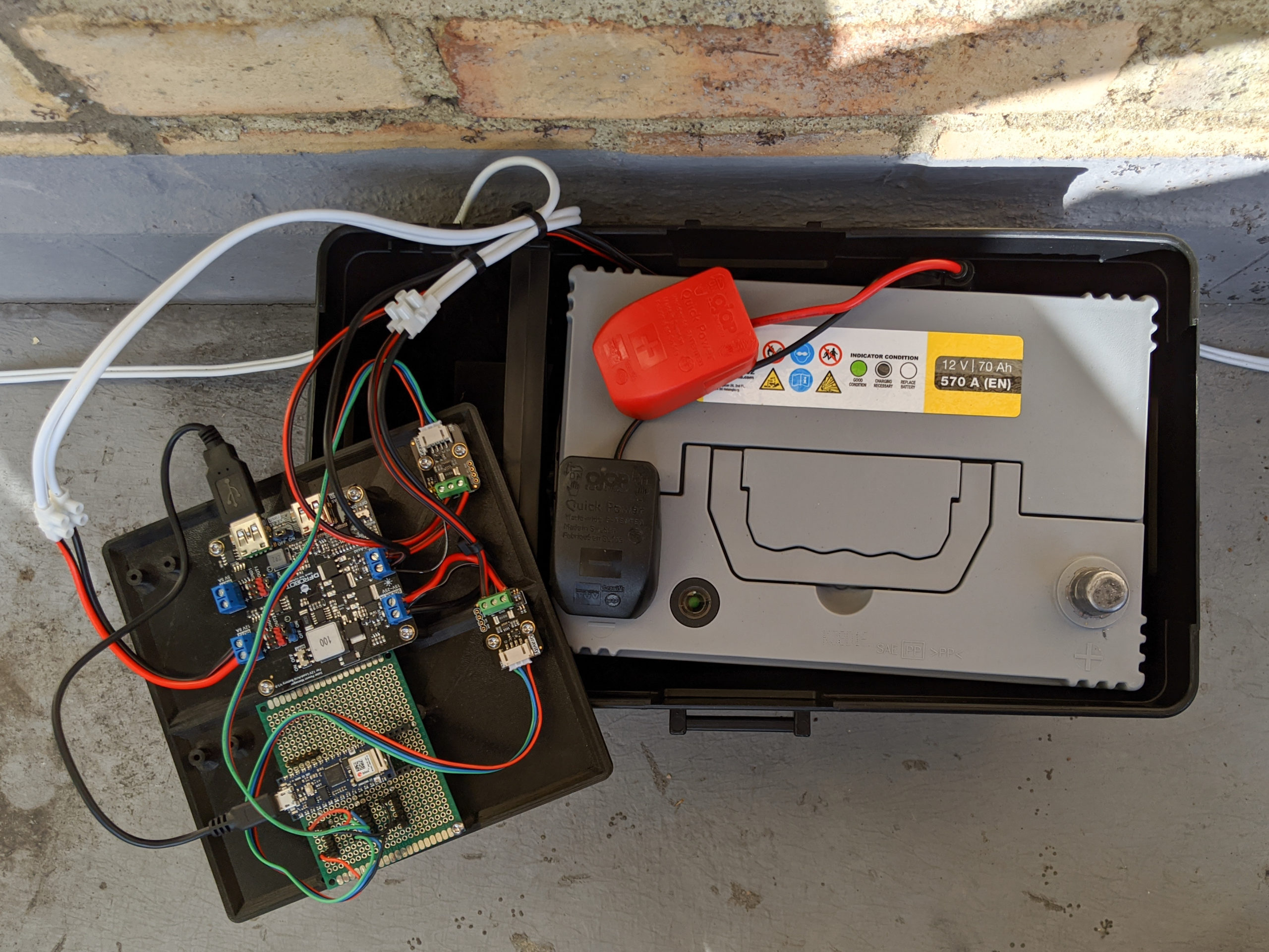
Biltema 12V 70Ah Lead Acid Battery (80-3702)
A generic deep cycle sealed maintenance free lead-acid battery. The datasheet doesn’t say much, and claims 3800 cycles at “light load”.
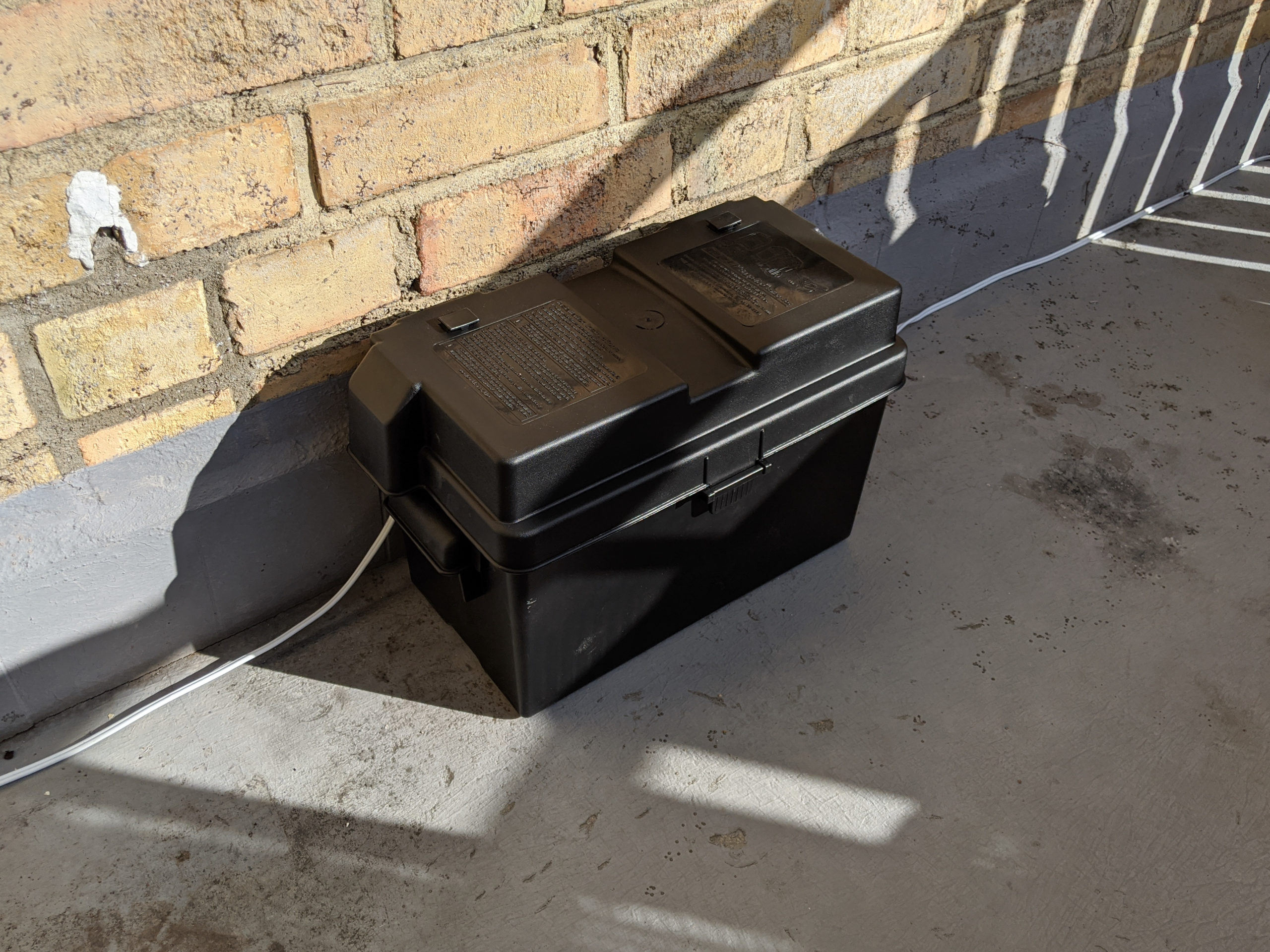
NOCO Genius HM318 Battery Box
A plastic battery box
Sunlux 50W Monocrystalline Solar Panel (SGM-50W-18V)
590 x 505 mm rigid solar panel in aluminum frame. This specific model is discontinued and is replaced by SGM-50W-20V.
DFRobot Solar Power Manager (DFR0580)
A pretty basic 4A lead-acid battery MPPT charger with 2 USB-A, 5V 5A and 8A low-side load switch outputs.
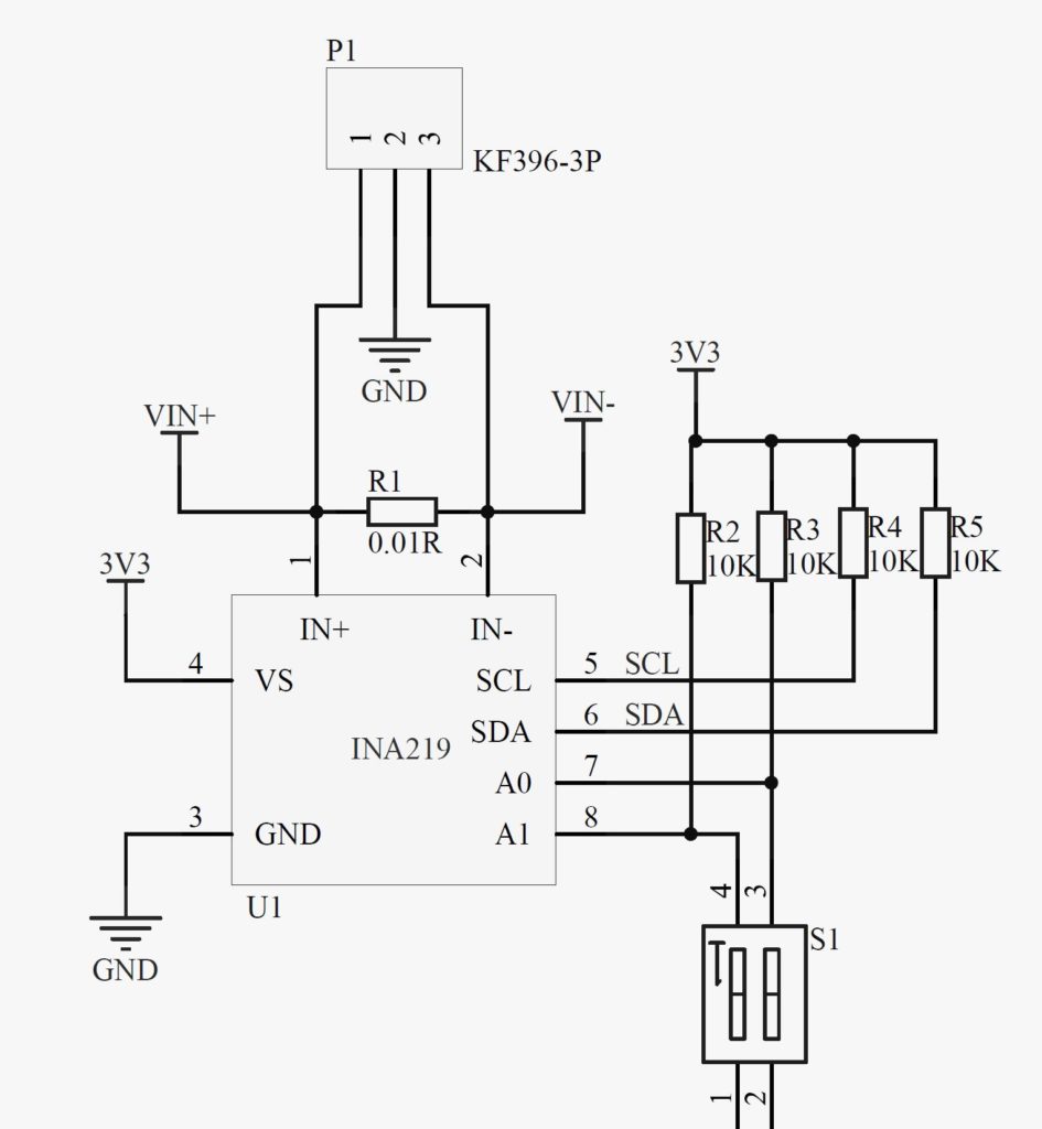
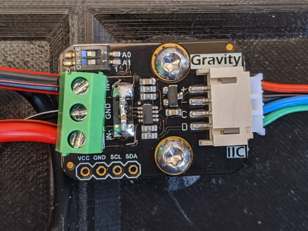
DFRobot I2C Wattmeter (SEN0291)
TI’s INA219 based current and voltage meter with I2C interface. Not very successful design, as it lacks any filtering, more about it further below.
Arduino Nano 33 IoT (ABX00027)
A small arduino with integrated Wi-Fi and Bluetooth.
Satechi 72W Type-C PD Car Charger (ST-TCPDCCS)
Car charger with one USB-C PD 60W and one USB-A 12W outputs.
Anker PowerDrive 2
Car charger with two USB-A 2x12W outputs.
Clas Ohlson Car Lighter Socket Splitter (36-3902)
Splits car lighter socket in two sockets. The plug is cut off, and only sockets are used in the project.
How it all works in hardware
The interconnections in the system are not very complicated and are shown on the block diagram to give a better understanding. The Anker Power Drive 2 charger is connected to the two Qi chargers, while the Satechi one is used for powering a laptop and charging other small devices. Everything except those chargers is located at the balcony.
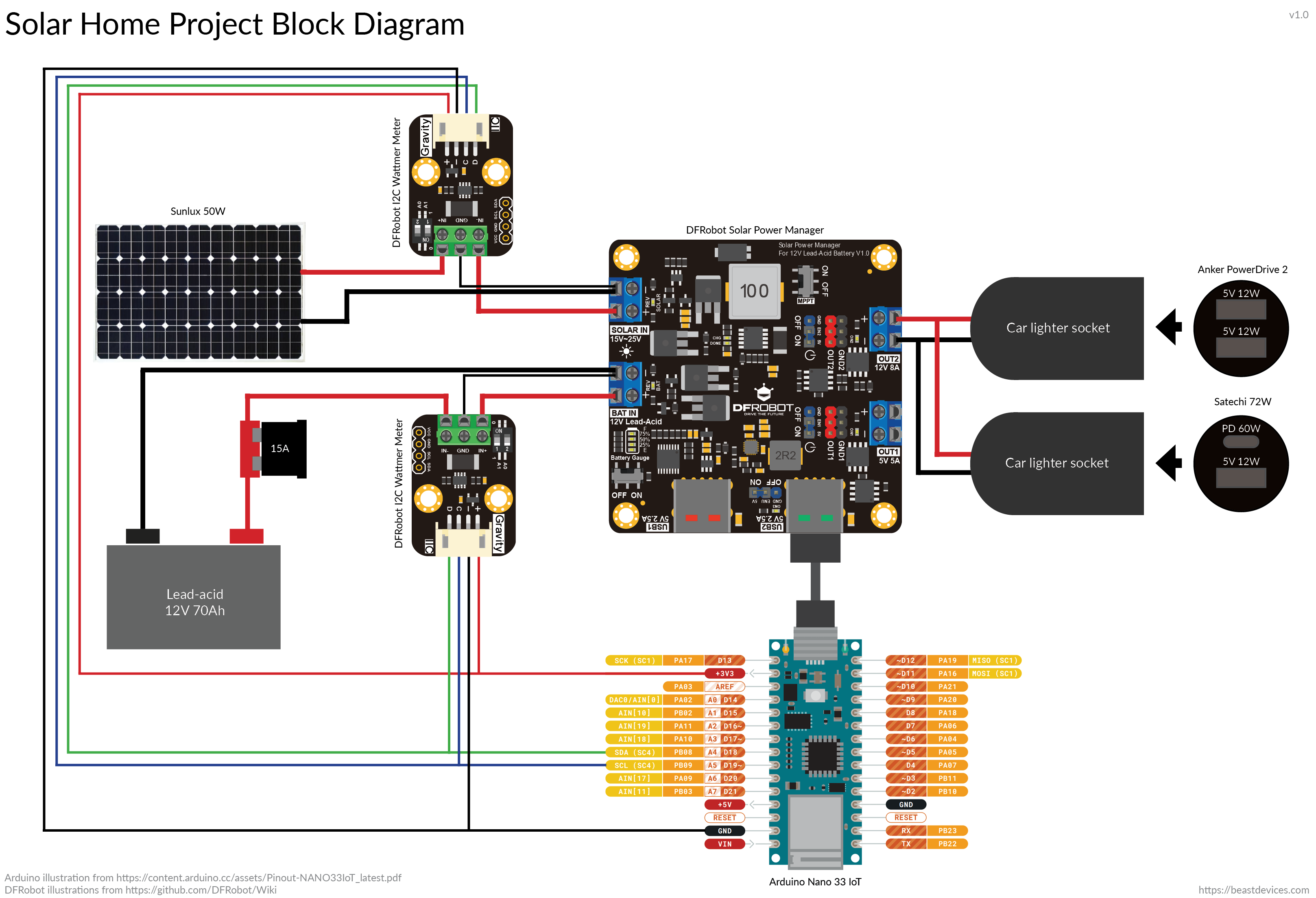
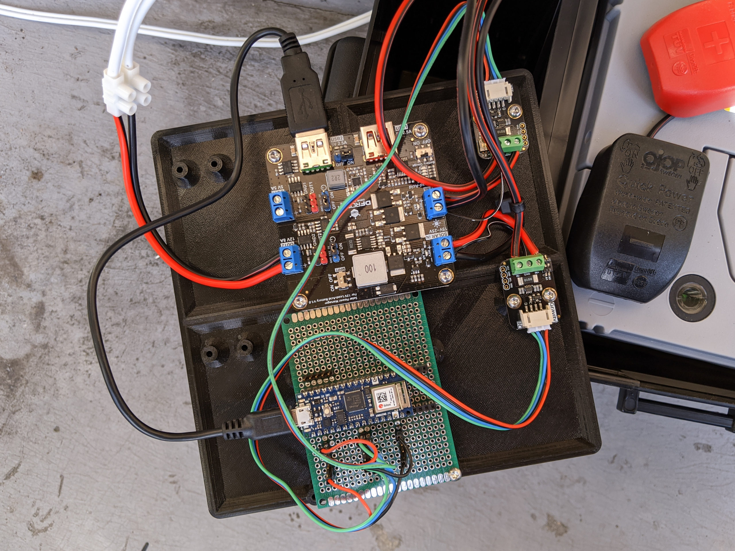
The components are mounted on a 3D printed mounting plate, which I have designed to fit the solar power manager, four wattmeters and a Raspberry Pi. I have mounted just two wattmeters and Arduino instead of Raspberry Pi. The mounting plate with components is placed together with a battery in the box. There are two wires going out of the box: one goes to the solar panel, and another goes inside of the apartment. I didn’t use the standard cable intended for the solar system installations, because those cables are single wire, and are usually black. Instead, I used a 1.5 mm2 (~AWG 16) CCA (Copper Clad Aluminum Wire) audio cable for interconnections inside of the box, and a 4.0 mm2 (~AWG 12) one outside of the box. At 10A it results in about 13mV drop per 1m of cable (both feed and return).

How it all works in software
The solar power manager is basic and can’t be programmed or monitored, so the system monitoring and control is handled by the Arduino. The two wattmeters measure current and voltage of the solar panel and the battery. Right now Arduino collects the data and sends it using HTTP GET to a server, where data is stored. The proper Arduino code and the server side is yet to be developed.
UPDATE May 30, 2020
I have updated code for Arduino, it uses MQQT instead of HTTP now. I have also set up Grafana with InfluxDB. The real-time graphs that you see in top are rendered each 5 minutes in Grafana.
Issues
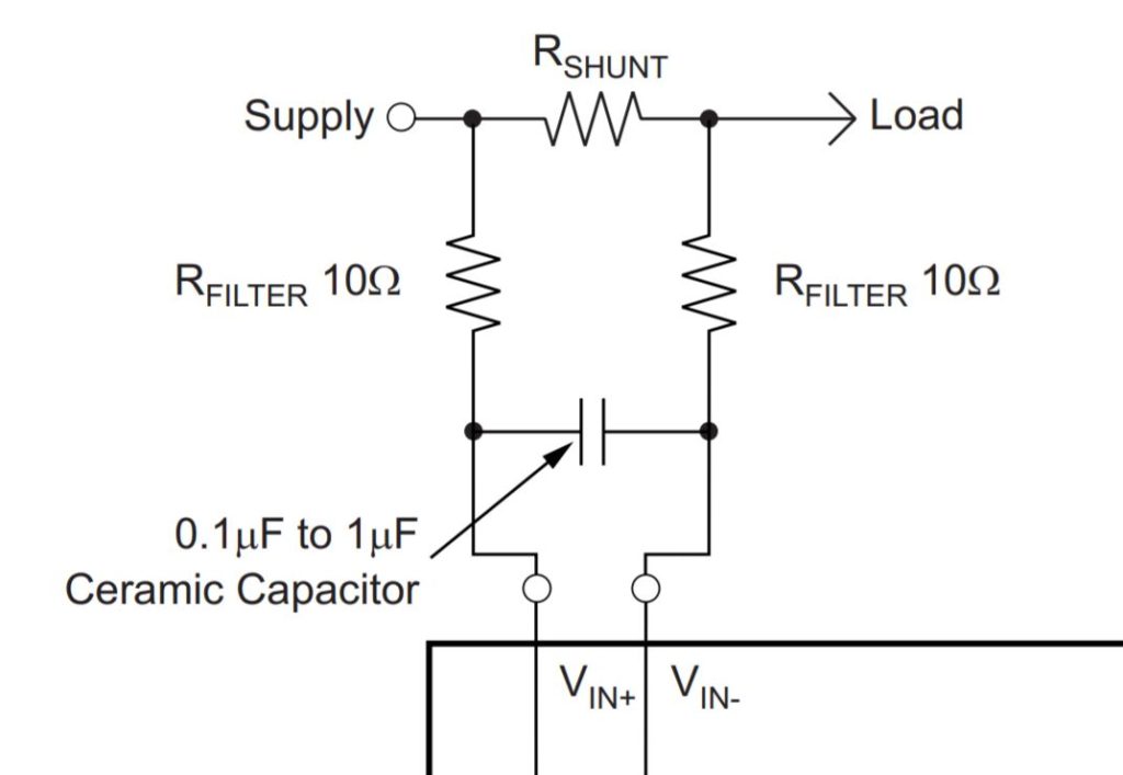
I have went through a couple of burnt wattmeters and a burnt Arduino. The issue would appear after connecting or disconnecting load (plugging or unplugging USB-C car charger). I was too lazy to make measuremens to determine the actual issue, so my first guess was that it could be transients across the current sense pins that damage INA219. I also assumed that damaged INA219 might have caused I2C lines to go over 3.3V, which would damage Arduino as well. After a closer look, it appears that the wattmeter doesn’t have any filtering on the INA219’s current sense differential input.
I added a basic filtering using two 1uF 25V ceramic capacitors in series across the current sense resistor. The reason for using two capacitors in series is to increase the voltage rating. Better filtering could be achieved by placing series resistors between IC’s differential pins and current sense resistor as shown below.
I have made couple of tests by plugging and unplugging USB-C car charger, and everything was fine. However, the following days I was trying out different chargers, and the INA219 broke again, which calls for making an actual investigation.
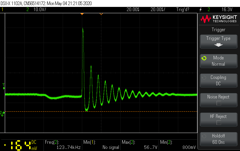
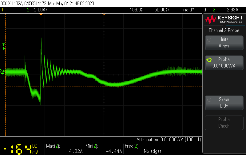
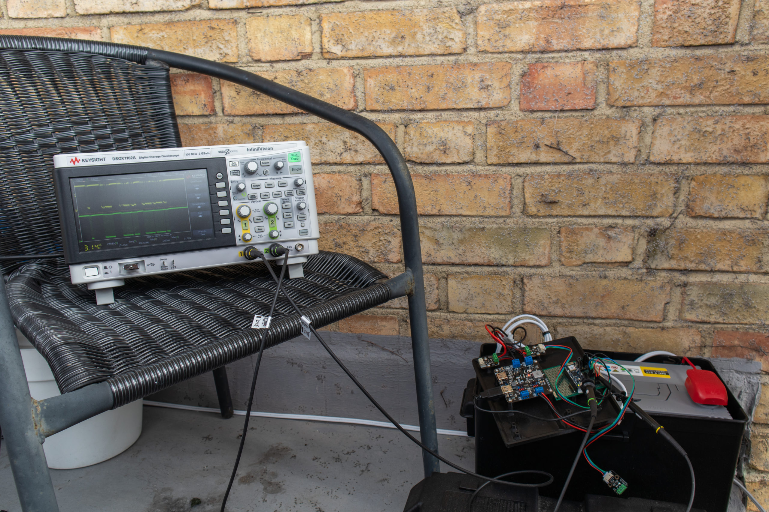
Hardware issue investigation
To investigate what causes the wattmeter to break, I have made a measurement setup on my balcony, because I didn’t want to relocate the system. I have made plenty of different measurements, collecting 67 oscilloscope screenshots. The conclusion is that the wattmeter breaks, because of the transient between GND and current sense resistor pins. The transient occurs when connecting a load, by inserting Anker or Satechi car charger in the cigarette lighter connector. The maximum voltage reaches 56.7V, which is way above absolute 26V maximum rating of INA219. Supposedly, the high inrush current is to blame. The issue can be most probably avoided by having a proper RC filtering around current sense resistor.


Hi Andrej! Great project and detailed explaination!!! I wanted to post my comment/request to this article. But it seems I was not able to do that (possibly because it’s very long?) I would like to deal with an extension to yout big portable PowerBank with an affordable Solar Panel + Wind Turbine + Battery circuit, in my case to “only” power a 300w (or more) Led Chip or Led Matrix. (to create a Flood Light). So I am sharing my long-request to you (and other readers if you want to post my full request manually) via “paste-bin”:… Read more »