Because there isn’t already enough of custom designed Raspberry Pi enclosures, I decided to design yet another one. The reason is because I want to fit a hard drive inside of it, and make it as compact as possible. I of course want to use the latest Raspberry Pi, and Raspberry Pi 4 is more power hungry compared to its predecessors and is more prone to thermal throttling at 80°C. Given that I want to have a hard drive in the same enclosure, while keeping it small and avoiding fans, thermal design became a bit of a challenge. I was going through the Internet, looking at different solutions, and then I got an idea, which is probably not that original.
The idea
What if instead of fitting a heat sink on Raspberry Pi, you would make a direct thermal contact between the plastic enclosure and CPU? In this way, instead of using the air to exchange the heat between CPU and enclosure, you could use thermal paste, or thermal pad, which has much better thermal conductivity than air. But now, of course, the area of enclosure that is used to exchange the heat is significantly smaller. Typical 3D printing filaments such as PLA, ABS and nylon, have thermal conductivity which is about 1000 times worse than that of aluminum. So, in addition to smaller area, low thermal conductivity of plastic might offset the benefit of better heat transfer between CPU and enclosure, or even make the total thermal performance worse. There is also a potential problem, because at 80°C majority of plastics might become too soft for any useful application.
The thermal performance can be, of course, improved by having ventilation holes in the enclosure. But this is already well-known fact. What I really got interested in, is if it is possible to improve the thermal performance in a sealed 3D printed plastic enclosure, by heat source having a direct thermal contact with the plastic.
I have been googling if anyone had any experience in trying to 3D print a plastic heatsink or something in that area. I have found some discussions, but I have not found any quantitative experiments, so, I decided to do my own.
The experiment
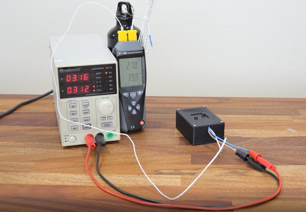
The experiment is quite simple. In the first case there is a sealed box with a heat source mounted inside of the box on one of the walls with a thermal pad in between. In the second case, there is the same sealed box and the same heat source, but the thermal pad is removed, and the heat source is mounted at some distance from the wall. To evaluate which one is better I will be measuring temperature of the heat source and the ambient air. Obviously, the lowest temperature difference between the heat source and the ambient air indicates the best thermal performance.
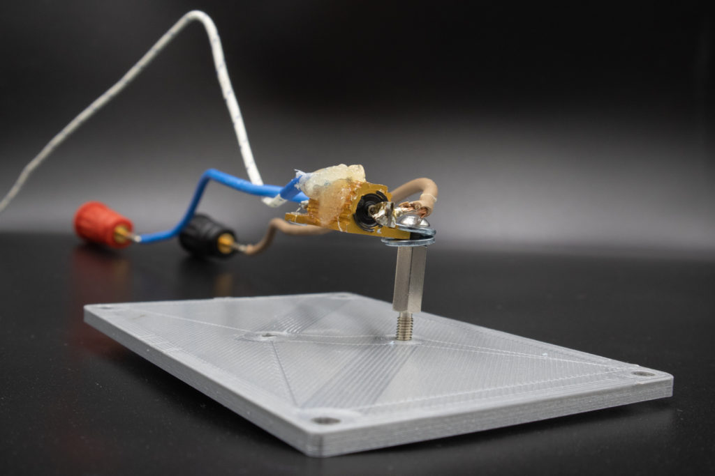
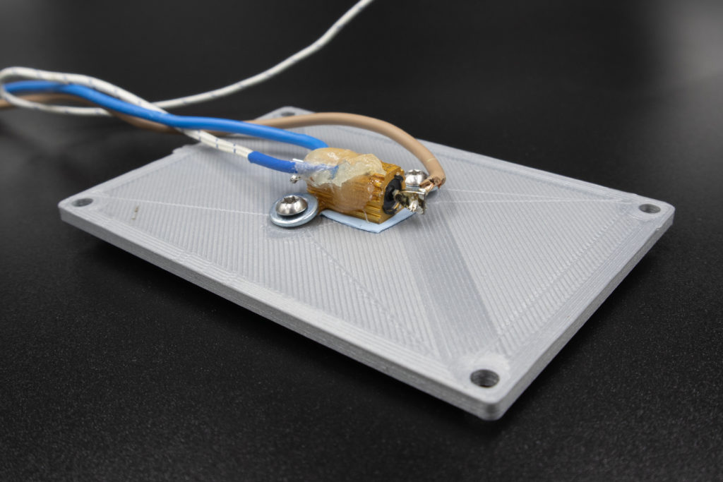
I am using a power resistor Arcol HS10 10R as a heat source because it is easy to mount it and to adjust the amount of heat delivered. I have glued a thermal couple to the resistor, and to measure both the temperature of the resistor and the ambient air, I am using a generic two channel thermocouple thermometer Clas Ohlson ET-959. I chose to use a thermal pad Multicomp MPGCS-030K-200-0.5 instead of a thermal paste, simply because it is less of a mess. The thermal pad is half-a-millimeter thick and has an unimpressive thermal conductivity of 3W/mK. The resistor is being fed with 1W of power, and the thermal pad area is about 2 cm2, so the added temperature difference will be at least about 0.8°C, which is insignificant.
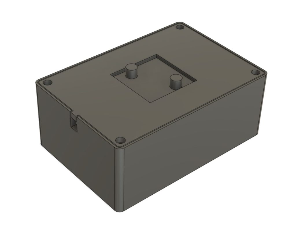
I have designed a box with 3-millimeter-thick walls, and the resistor is mounted on the lid. The footprint size of the box is 65 x 95 mm, and the height is 40 mm. The size of the box is chosen to be similar to Raspberry Pi enclosure. I chose to mount the resistor on the lid on purpose, because it is easier to mount, and faster to print a new lid if another mounting solution is needed. In the place, where resistor is mounted, the wall thickness is reduced to 1 mm to improve the thermal performance.
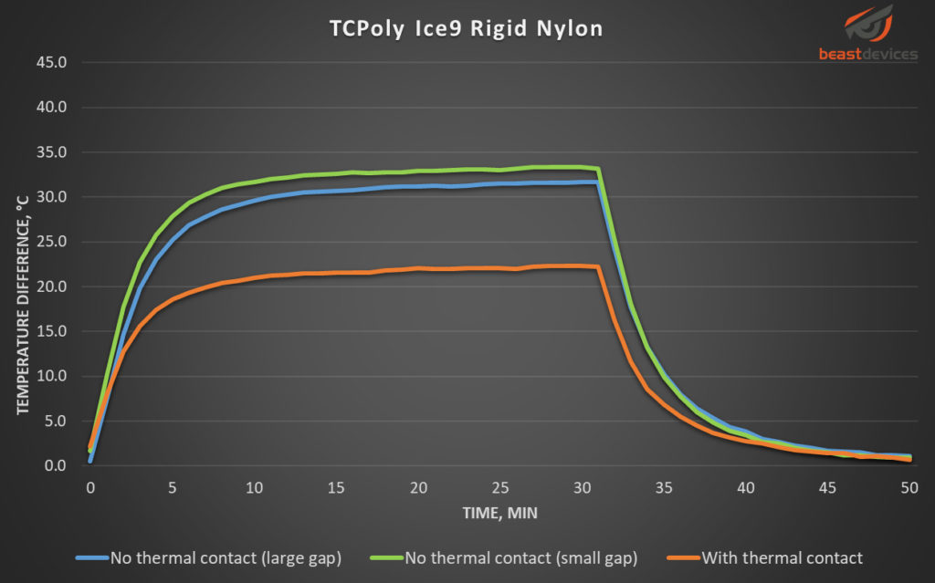
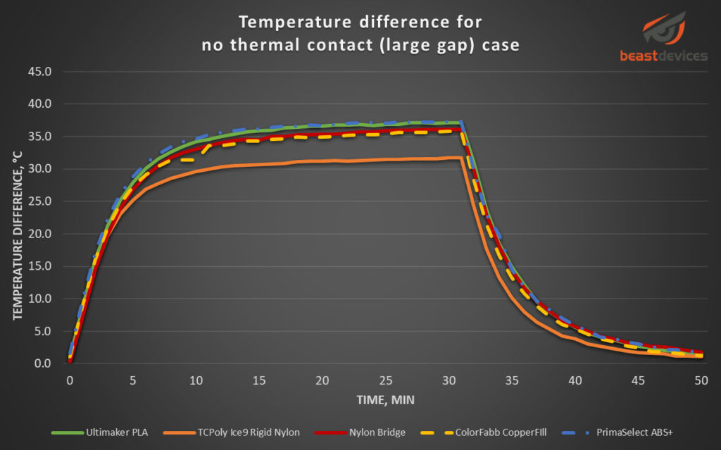
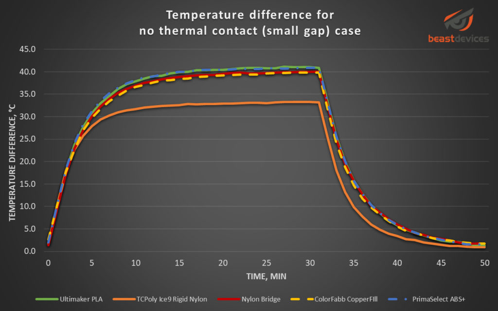
I have 3D printed five boxes to compare thermal conductivity of different materials and to simply have more data. I’m testing well known Ultimaker PLA, Colorfabb CopperFill PLA, PrimaSelect ABS, Bridge Nylon, and also less known TCPoly Ice9 Rigid Nylon. I chose to test the copper filled filament, because there were some speculations, that it has better thermal conductivity than regular PLA, because of the copper particles in it. I was skeptical about it because there is still plastic between the metal particles. But I wanted to test it anyway. The TCpoly filament is specifically designed to be more thermally conductive and is about 5 to 20 times better depending on how it is printed, but it also costs 140 dollars for half a kilogram with shipping. This is the most expensive filament I have ever bought, but I wanted to try it anyways to see if it does what it says and if it is actually possible to print it on my 3D printer.

It would be the best to perform these experiments in a climate controlled chamber, but I don’t have one, and I’m not going to buy one just for couple of experiments, so I have to work with what I have. I have minimized the airflow in the room, by turning off the ventilation, closing the windows and curtains. The setup is not fancy, but I think it is good enough for the purpose.
In each experiment I gave it 30 minutes to warm up, and 20 minutes to cool down. It is enough for the temperature to stabilize. During measurements I have realized that the setup without thermal pad is incorrect, because the distance between the enclosure and the resistor is too large. It results in a lower temperature of the resistor because temperature inside of the enclosure is highest in the top and lowest in the bottom. So, I had to redo the measurements, by having just a small couple of millimeters gap between the resistor and the enclosure. This resulted in three test cases, instead of two:
- No thermal contact (large gap, about in the middle of the box)
- No thermal contact (small gap, 2-3 mm from the wall)
- With thermal contact

The results
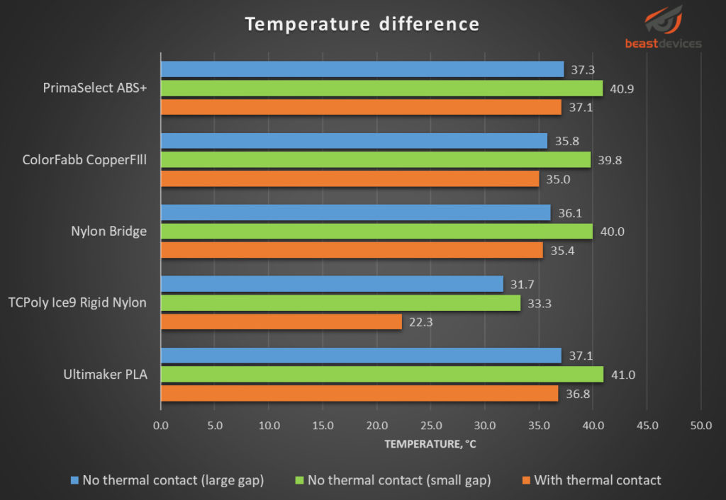
If you look at all materials in the graph below, you can notice that for all 5 of them, the temperature difference for the test case when resistor is mounted with a small gap (green bars), is the highest; and the temperature for the case when resistor is mounted with a thermal pad (orange bars), is the lowest. This consistency leads to a conclusion that the resistor being mounted directly on the enclosure provides maybe not incredibly significant, but definitely better thermal performance.
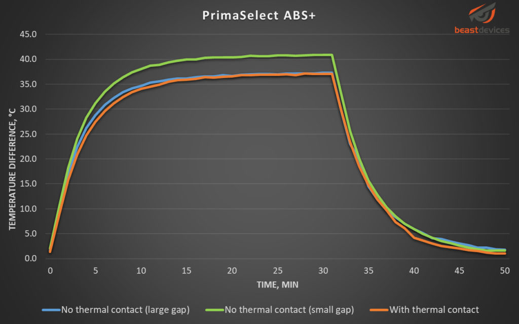
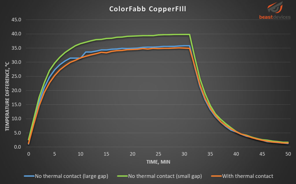
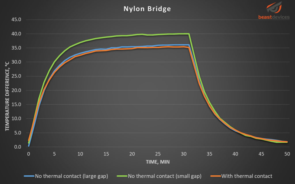
The following graphs show the temperature difference change over time for the materials tested. The temperature difference is between the ambient air and the resistor.

These following graphs plot the same data, as the previous ones, but in a different way. Each graph represents one test case for all materials.
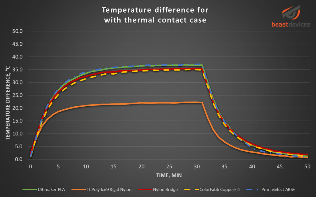
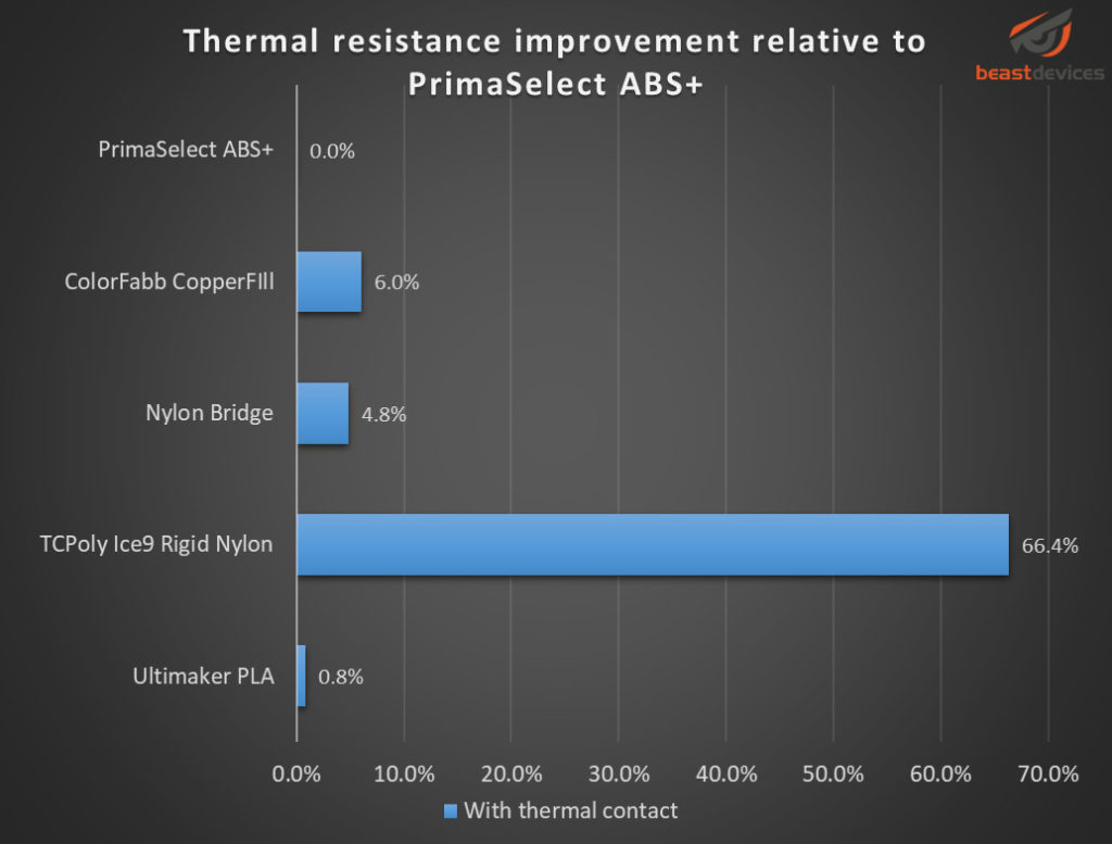
This graph below shows the improvement of the thermal performance by comparing two test cases: no thermal contact (small gap) and with thermal contact. The improvement of the thermal performance is calculated by subtracting the temperature difference between two cases, and then dividing the result by the temperature difference for the no thermal contact (small gap) case. To give an example, for the PrimaSelect ABS+, using the number from this graph the improvement is going to be (40.9 – 37.1)/37.1 = 10.24%. As another example, if the improvement is 100%, it means the temperature difference has dropped to a half.

The last graph shows the improvement of the thermal performance compared to the PrimaSelect ABS+. The comparison is for the no thermal contact (small gap) case.
These results can, of course, be affected both positively and negatively depending on the printing settings, thermal pad and all sorts of other factors. Also, the figures will be probably different, if the box is standing on its side, or upside down. But it takes a lot of time to do all possible test cases, so I will leave it for later or someone else to do it.
From the practical point view, I cannot really come up with any application for the PLA and Nylon, because these materials are so soft at higher temperatures. The ABS, however, even having the worst performance of all tested, is cheap, and has more potential to tolerate 80°C temperatures. The TCPoly filament is impressive, and can tolerate high temperatures, but considering the high cost, I am not sure it is within the reach for most of the projects.

I always find myself nodding along and agreeing with your wise words Your insights and advice are truly valuable
Which printer did you use for TC Poly nylon filament?
Your honesty and vulnerability in sharing your personal experiences is truly admirable It takes courage to open up and I applaud you for it