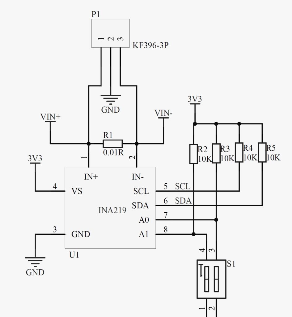
Following my experiments with setting up a small-scale solar system for charging phones and laptops, I needed a better power meter. I am using a DFRobot I2C Wattmeter (SEN0291) to measure current and voltage of a battery, a solar panel and a load. It is INA219 based, and has as minimilastic design as other INA219 based boards from Adafruit, Sparkfun or other manufacturers.
The problem with power meters
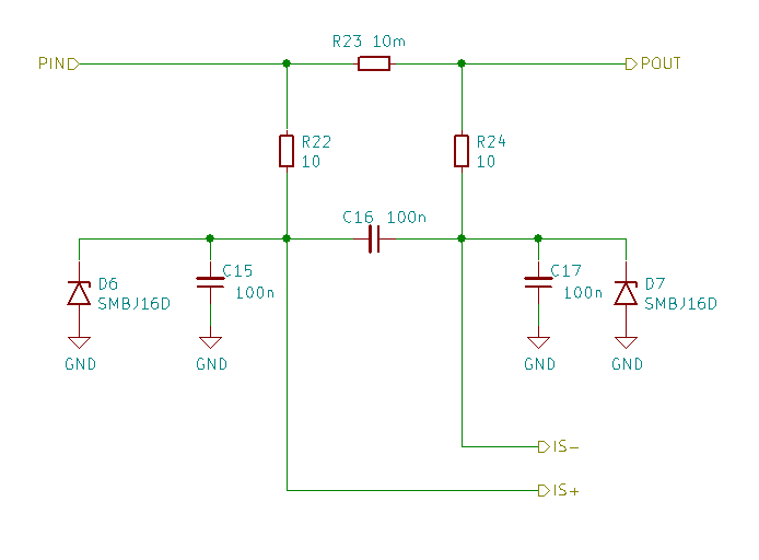
The problem with all of these boards, is that there is no filtering implemented around the current sense resistor. The pins of INA219 are directly exposed to the voltage on a wire you are trying to measure the current of. If there is any transient voltage higher than 26V between the current sense resistor and ground, the INA219 will be destroyed.
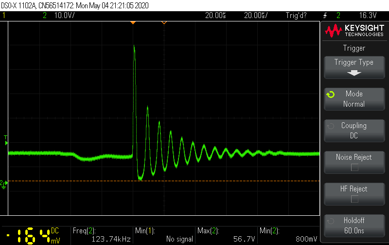
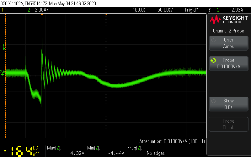
In my case, the module would get sometimes destroyed during connection of a load. I have measured the voltage between the current sense resistor and ground during load connection, and maximum voltage reaches 56.7V, which is way above 26V. My conclusion was that it is caused by the high inrush current oscillations.
Another disadvantage with all these prototyping modules are the connectors. The screw terminals are low quality, too small and don’t provide in and out connections for both power and ground.
Trying to find something good
After endlessly trying to find something good for a reasonable price, there wasn’t anything. But while searching, I found that INA3221 seems to be used in some prototyping modules as well. It is basically INA219, but with three channels, instead of one.
I have also discovered that Adafruit’s Feathers are gaining more popularity. If you are not familiar, it is an ecosystem, where Feathers typically feature an MCU, LiPo charger and USB connection. FeatherWings are shields, which can feature wireless modules, displays, realys etc. Kind of similar to Arduino ecosystem.
So the choice was obvious. I started designing the power meter around INA3221, which also acts as a FeatherWing. In this way I can connect one of the Feathers with Wi-Fi, for example, Adafruit HUZZAH32 to log data to my Grafana based monitoring system.
Designing a tougher power meter
The power meter has three channels, each capable of continuous 10A and 24V. Each channel has proper RC filtering with TVS diodes. One of the channels has a TPS1HB08A power switch, to be able to disconnect the load. The board can also provide power to the Feather from one of the channels.
The connectors are pluggable screw terminals from TE (796639-2). Each channel has one input and two parallel outputs for both power and ground. Of course, the ground is shared between all three channels.
So far, I have finished the schematics and began routing the PCB in KiCAD.